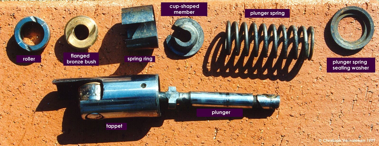
The circular foot of the plunger carries a floating
cup-shaped member which centres and retains the plunger spring. This cup also serves as a
carrier for the hardened steel self-aligning pad which is interposed between the end of
the plunger and the head of the tappet. Tappets are furnished with a profiled roller
running on a flanged bronze bush mounted on a steel pin. Pin, bush and roller are
assembled with running clearances. The flange of the bronze bush, serving as a thrust
member between the face of the roller and the side of the tappet, is provided with radial
oil grooves on each side. Registered and riveted to the flange of the splinted drive
shaft, the face-type actuation cam takes its bearing on a bronze bush pressed on the
reduced end of the tappet housing half of the body. The forward face of the cam provides
one track for a full diameter ball-thrust race. The other track is, of course, registered
on the mounting flange of the unit, which completes the body structure and carries oil and
seal for the drive shaft.
To avoid rotation of the tappet and consequent misalignment of the rollers in relation to
the cam, each tappet is provided with a segmental extension, the ground edges of which
loosely engage a split ring positioned concentrically around the cam and supported in the
body casting. By way of drillings in the mounting flange and the body casting, oil from
the engine lubrication system is delivered to the tappet enclosure for lubricating the
actuating gear.
The fuel eventually enters the fuel injection line
via a pressure valve. It rests on the pump barrel with its completely plane and
hard-chromed side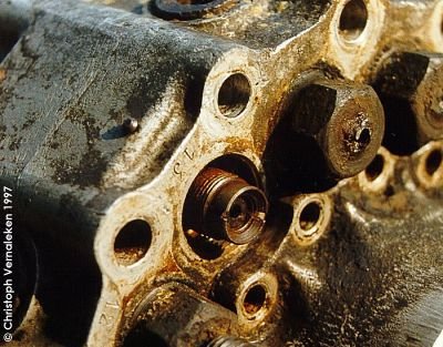 . It is covered by a 19 mm special screw. One side of
it sits in the aluminum casing (M22×1.5) and features the connector for the fuel
injection line on its other end (M12×1.5). In order to prevent these special screws from
moving, they were secured by so-called "Sicherungshülsen" No. 9-2106.90-20
already removed in the picture. There is a picture of this part in the following section.
The photo to the left shows the damaged screw of cylinder #14 and the pressure valve of
cylinder 13. Cylinder #11's screw is still intact, but not fully in the picture. A rivet
protrudes from the plane area slightly left above the "13" in the casing. It
once held the manufacturer's tag.
. It is covered by a 19 mm special screw. One side of
it sits in the aluminum casing (M22×1.5) and features the connector for the fuel
injection line on its other end (M12×1.5). In order to prevent these special screws from
moving, they were secured by so-called "Sicherungshülsen" No. 9-2106.90-20
already removed in the picture. There is a picture of this part in the following section.
The photo to the left shows the damaged screw of cylinder #14 and the pressure valve of
cylinder 13. Cylinder #11's screw is still intact, but not fully in the picture. A rivet
protrudes from the plane area slightly left above the "13" in the casing. It
once held the manufacturer's tag.
Before dismantling the pump, l inserted it into MoS2 for about a month.
Currently, the pump is almost completely dismantled. Three pump barrels still remain in
the casing, and the aluminum parts have to be polished and preserved. Up to now, I spent
some 200 hours on the restoration of this intricate device.
If you are interested in the progress of restoration work, click here to get to the next page...